Description
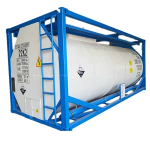
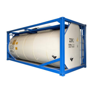
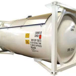
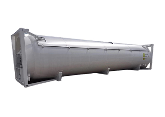
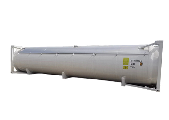
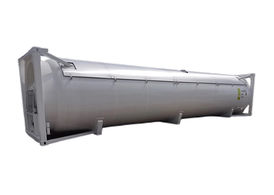
The 40-foot T50 LPG tank container is designed for the safe and efficient transportation of liquefied petroleum gas (LPG). One of its primary advantages is its robust construction, utilizing high-strength carbon steel to withstand high pressure and extreme environmental condition.
This T50 tank container equipped with advanced safety features, such as pressure relief valves and advanced monitoring systems, this LPG tank container ensures compliance with international safety standards. Its large capacity optimizes logistics efficiency, reducing transportation costs per unit.
Additionally, the 40-foot design allows for easy handling and compatibility with various transport modes, including ships, trucks, and trains. with BV, CCS, LR certificate.
|
Specifications – 40′ iso tank container
|
||
|
Frame Dimensions (L x W x H)
|
12192 x 2438 x 2591 mm
|
|
|
Nominal Capacity
|
52500 litres (approx)
|
|
|
Maximum Gross Mass
|
36000 kgs
|
|
|
Tare Mass (Nominal)
|
12,000 kgs (with baffles) (+/- 3% tolerance)
|
|
|
Design Temperature (Frame & Tank)
|
-40 to + 55 °C
|
|
|
Pressure
|
Working pressure
|
18 bar
|
|
Test pressure
|
25.7 bar
|
|
|
Material
|
Tank
|
Shell & Heads: SA612N; Flanges: SA350LF2
|
|
Headframes
|
Q345D or equivalent
|
|
|
Manhole |
– One (1) manhole at rear end of the container – DN500 inside diameter, with bolted cover
– Spiral wound gasket (PTFE/304)
|
|
|
Safety Relief Valve |
– One (1) flange for safety relief valve on top of tank (approx 18 offset from vertical center-line. – Size DN80, equipped with Fort Vale relief valve (FV 015/22615F), Fort Vale Bursting Disc, manometer (FV920/20TTBBSPDRY), and custom seals.
– Gasket PTFE.
|
|
|
Liquid Line
|
– One (1) flange 2″ (DN50) for internal bottom valve and external a manual operated
Fort Vale 2″ ball valve (FV 802B/0010L) – Internally a dip pipe to the bottom of the tank, with sump in tank-wall
– Gasket PTFE/304.
– Ball valve provided with blind flange and 3¼” ACME coupling with cap
– One (1) purge cock on the ACME coupling.
|
|
|
Gas Line
|
– One (1) flange 2″ (DN50) for internal bottom valve and external a manual operated
Fort Vale 2″ ball valve (FV 802B/0010R) – Internally a stand pipe to the gas phase
– Gasket PTFE/304.
– Ball valve provided with blind flange and 1¾” ACME coupling with cap
– One (1) purge cock on the ACME coupling.
|
|
|
Manometer
|
– One (1) ½” connection for pressure gauge, connected to the gas phase of the tank. – External a DN15 ball valve and a ¼’ manometer 0-40 Bar (FV 920/40RBSP)
|
|
|
Thermometer
|
– One (1) ½” connection for pressure gauge – Thermometer range -40 to +100 ºC and -40 to +212 ºF, dual scale
|
|
|
Design Code
|
ASME VIII Div. 2 with ASME U2-Stamp
|
|
|
Design Approval
|
Lloyds Register or BUREAU
|
|