Description
lng iso tanks
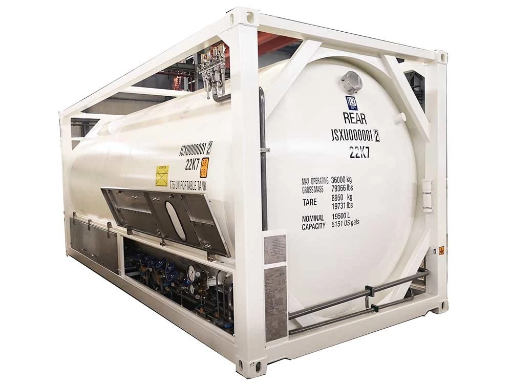
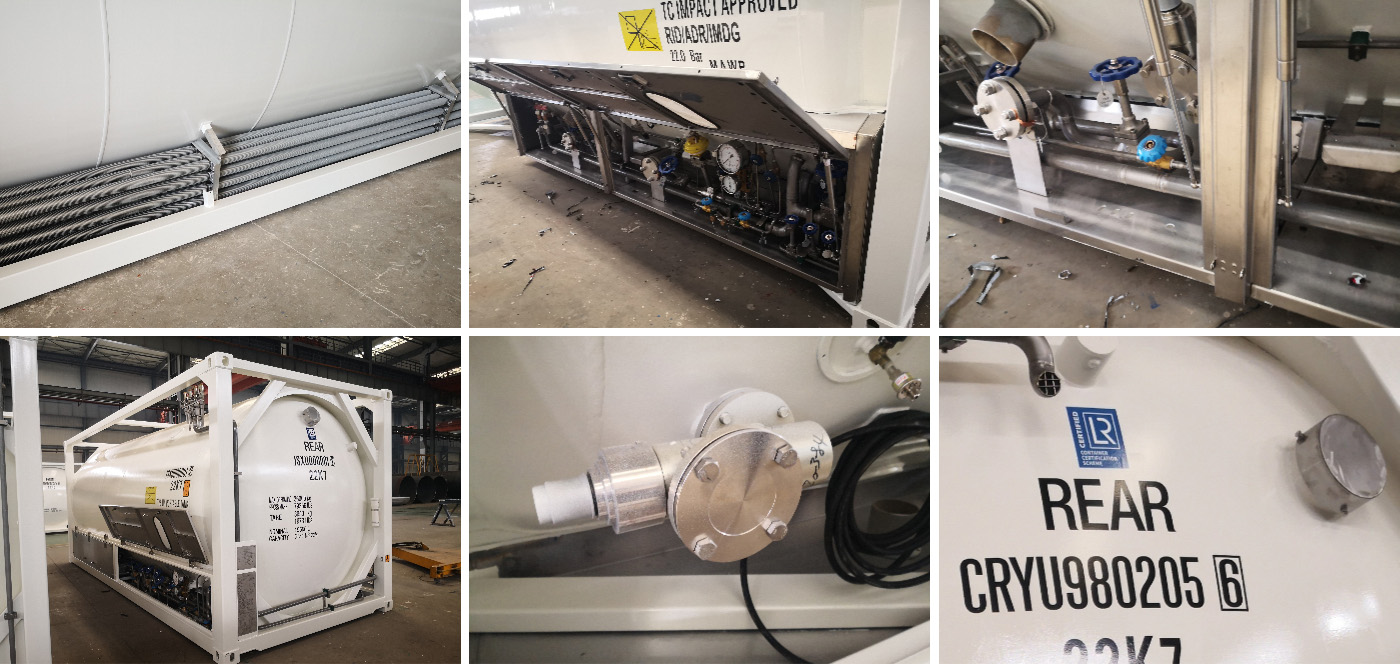
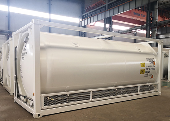
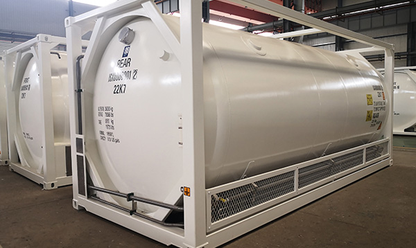
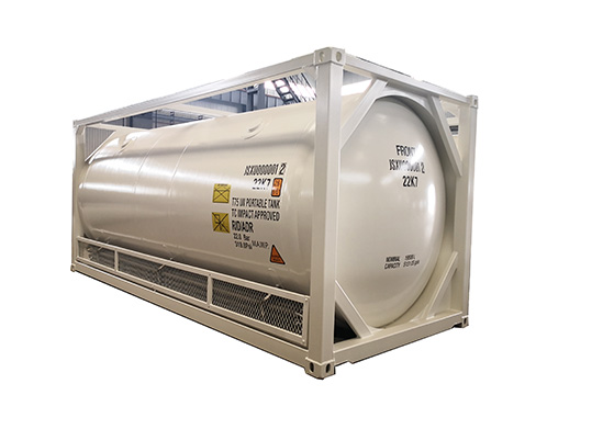
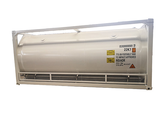
lng iso tanks T75 ASME standard LOX LIN LAR LNG LCO2 iso tank container 20ft
Product Details:
CRYOGENIC TANKS
Storage tank is for liquefied gas under pressure, at cryogenic temperatures,
for products, such as LNG, N2, O2, Ar, CO2.
They consist of two vessels, one inside the other, with robust thermal insulation
in the chamber between them. They are built in
both a vertical (with legs or skirting ) and horizontal version(with support cradles
and anchoring to the ground).
Design
According to ASME, GB150-98 standards.
Inner pressure vessel
A vessel usually made stainless steel or other materials that have favorable strength
characteristics when exposed to cryogenic temperatures.
Insulation
Heat insulation is provided by a filling in the chamber between the two vessels
using insulating material and a high vacuum. It includes absorbent material for
greater vacuum stability. The effective thermal insulation minimizes product
losses and enables lengthy storage times of low temperature liquefied gases.
Outer vessel
A vessel made of carbon steel or stainless steel. Under normal operating
conditions, this vessel retains the insulation around the inner pressure vessel,
and can also maintain a vacuum around the inner vessel. Typically,
the outer vessel is not exposed to cryogenic temperature.
parameter:
| Specification | 1. | ||||||||||||||||||||
| Design standard | IMDG-CODE, GB150-98 | 2. | |||||||||||||||||||
| Recognized register | CCS | 3. | |||||||||||||||||||
| Tank shape | Column shape, horizontal | 4. | |||||||||||||||||||
| Size | 20/40 feet, tank type | 5. | |||||||||||||||||||
| Dimension | 6058 x 2438 x 2591 mm; 12192 x 2438 x 2591 mm | 6. | |||||||||||||||||||
| Capacity | 19800/46500 liters | 7. | |||||||||||||||||||
| Loading medium | LNG/O2/N2/N2O/CO2/Ar storage and transport | 8. | |||||||||||||||||||
| Tare weight | 11050/14000 kg | 9. | |||||||||||||||||||
| Payload | 22950/20000 kg | 10. | |||||||||||||||||||
| Gross weight | 34000 kg | Standard Configuration | 1. | ||||||||||||||||||
| Design pressure | 2.21 Mpa | 2. | |||||||||||||||||||
| Working pressure | 20 feet, 1.6 Mpa; 40 feet, 0.6 Mpa | 3. | |||||||||||||||||||
| Test pressure | 20 feet, 1.6 Mpa; 40 feet, 1.0 Mpa, hydraulic pressure test | 4. | |||||||||||||||||||
| Gastight test pressure | 1.44 Mpa | 5. | |||||||||||||||||||
| Vacuum test pressure | 0.1 Mpa | 6. | |||||||||||||||||||
| Design temperature | -196 to 55 celsius | 7. | |||||||||||||||||||
| Working temperature | -162 to 50 celsius | 8. | |||||||||||||||||||
| Corrosion degree | 0 | 9. | |||||||||||||||||||
| Welding joint efficiency | 1.0 | 10. | |||||||||||||||||||
| radio graphic inspection | 100% X-RAY | 11. | |||||||||||||||||||
| Tank material | SA-240 304, SA-516 70, double layer, 20 feet, 16/6 mm; 40 feet, 7 mm | 12. | |||||||||||||||||||
| End enclosure | 20 feet, 18/8 mm; 40 feet, 8 mm | 13. | |||||||||||||||||||
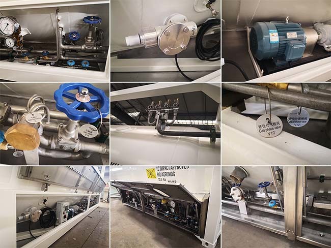
| Compound manhole | DN500 | 14. | |||||||||||||||||||
| Safety valve | DN25 | 15. | |||||||||||||||||||
| Gas phase valve | 20 feet, DN40; 40 feet, DN50 | 16. | |||||||||||||||||||
| Liquid valve | 20 feet, DN40; 40 feet, DN50 | 17. | |||||||||||||||||||
| Pressure gage | Y100, 1 pc | 18. | |||||||||||||||||||
| Thermometer | WSS412, 1 pc | 19. | |||||||||||||||||||
| Static evaporation rate | 20 feet, less than 0.18%/d; 40 feet, less than 0.225%/d | ||||||||||||||||||||
| 20. | |||||||||||||||||||||